Learning subnetting with GNS3 Part 1: Installation and Setup
While studying subnetting for the CompTIA Network+ Exam, I wanted a way to put what I was learning into practice in a simulated environment. Rather than simply doing subnet math in my head and on paper, I was looking for some type of lab in which to experiment. Cisco packet tracer is a potential option, but I wanted something vendor-neutral. That is how I came across GNS3. GNS3 is software that allows you to sandbox network environments. You can add virtual switches, routers, PCs, and a host of other devices. This was perfect for my needs.
In order to get started, I wanted to put together a simple network with two subnets and a router. GNS3 makes available a “VPC” with is a very small VM with minimal functionality that is great for quick prototyping. These have a small number of command-line network tools like ping that you can use. The GNS3 website has a tutorial for building your first virtual network, but it is fairly simple, with only VPCs and a single switch. I wanted to build something a bit more complex for subnetting, but I struggled to find the right tutorial. I hope this post can help anyone looking to do something similar.
Installation
First we need to install GNS3 on our machine. This tutorial will assume you are using Linux (specifically Ubuntu 20.04). Installation will depend upon what OS you are using, but you can find installation instructions on the GNS3 website. The installation instructions for Ubuntu-based Linux distributions can be found here. If you are on Windows, the installation process is a bit different, but once installed you should still be able to follow along with the tutorial. You can find the Windows installation instructions here.
Setting up a project
When that is complete, go ahead and starts GNS3. You should be greeted with a screen that look like this:
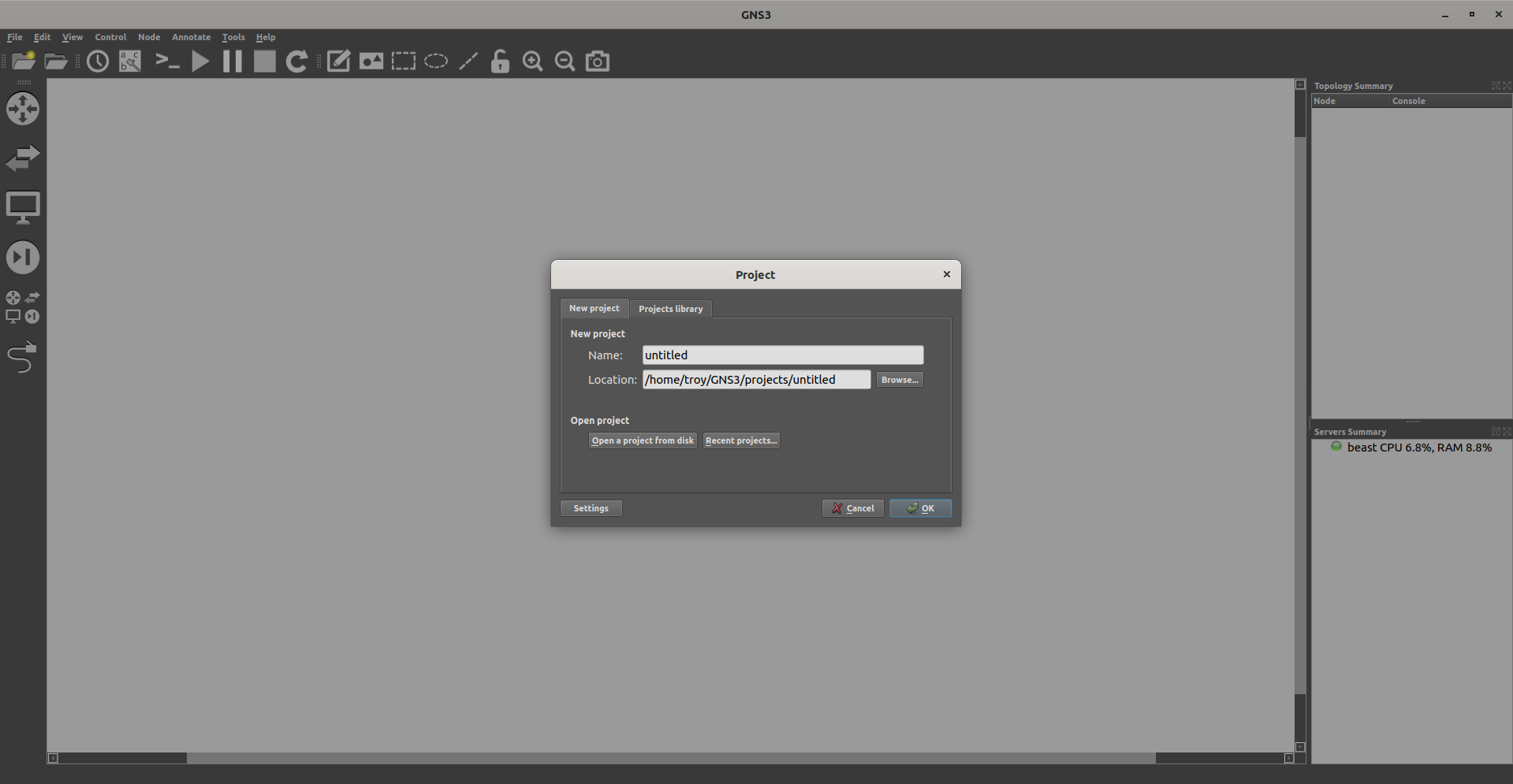
Choose a name for your project (I chose “sandbox”) and click OK.
Installing appliances
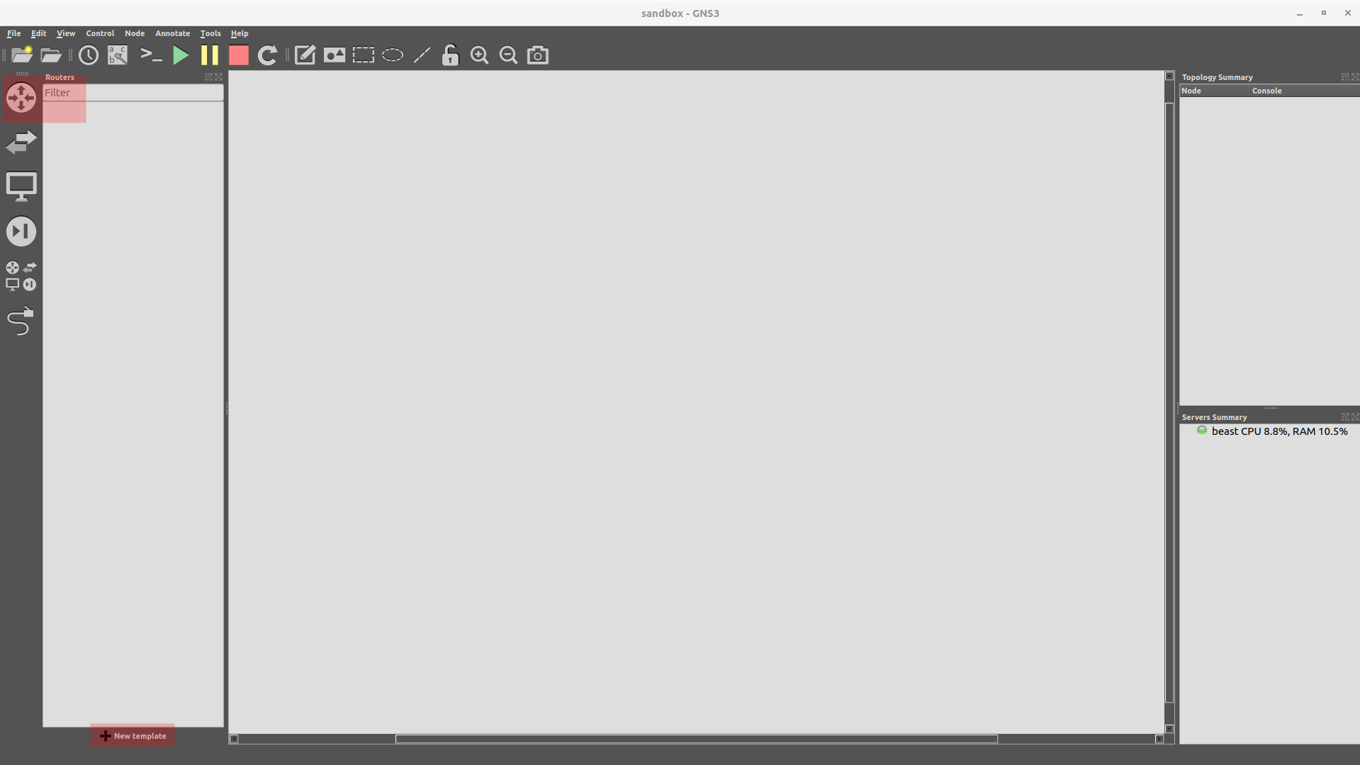
There are three virtual devices that we will need for this project-a virtual PC, a switch, and a router. The virtual PC and switch are already installed into GNS3, but we will need to import a router appliance. I chose the OpenWRT router appliance for this project. To import, click on the router symbol at the top left, then click “New Template” at the bottom.
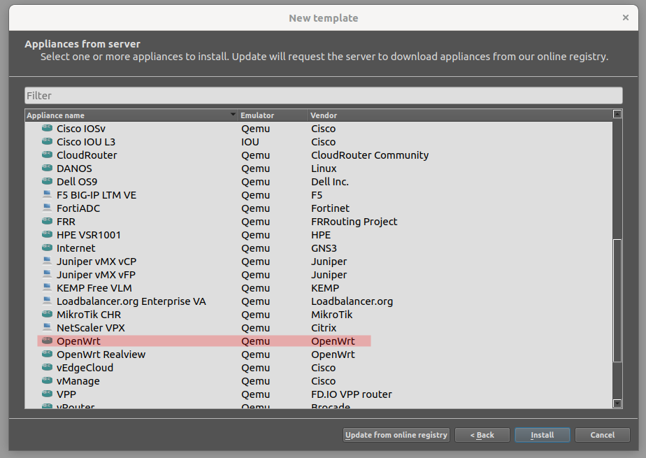
When prompted, choose “Install an appliance from the GNS3 server”, then click next. Expand the “Routers” entry in the tree and scroll down until you find “OpenWRT” in the list, then click Install.
When prompted, choose “Install the appliance on your local computer”, then click Next. When prompted to choose a Qemu binary, leave it as the default and again click Next. On the next screen, select the top item in the list and then click Next.

It will then ask if you want to install OpenWrt. Click Yes.
After a few seconds, you should get a message that the installation was succesful and the template was created. Click OK. We now have everything we needs and are ready to start building our first network topology.
Building a network topology
Again click on the router symbol at the top left. You should now see OpenWrt in the list. Click and drag it to the center of our work area. Then right click on the newly-placed router and select “change hostname.” In the box type “R1” and click Ok.

Now return to the left side menu and select the switch denoted by two arrows facing opposite directions. Drag and drop two “Ethernet switch” devices on either side of R1. We’ll use the default names of Switch1 and Switch2. Strictly speaking we don’t need the switches for this project, but if we want to expand our project and add more than one virtual PC on each subnet, we will need them later.
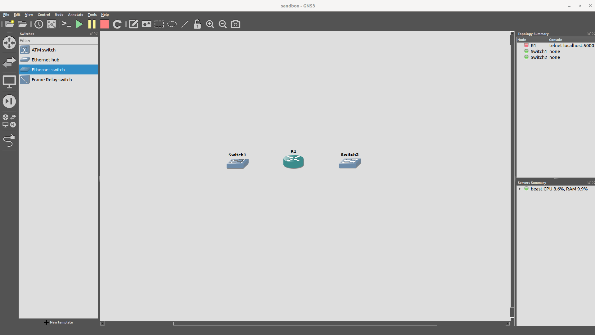
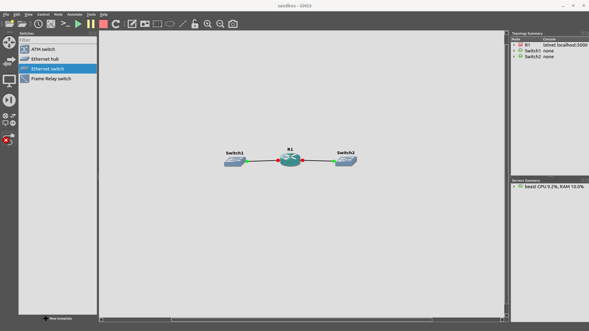
Now we need to connect our switches to the router R1. On the left side, select the symbol that looks like a cable with an RJ-45 connector on the end. Then left-click Switch1 and select “Ethernet0” from the drop down list. Move over to R1, left-click and select “Ethernet0” from the list. Then left-click R1 and select “Ethernet2” from the drop down list. Finally move over to Switch1, left-click and select “Ethernet0” from the drop-down list. Notice that we are not using the “Ethernet1” interface on the router, since that is the designated WAN link. Your setup should now look something like this:
Finally, we are going to add some virtual PCs to our topology. The virtual PC is a lightweight simulator with some basic command-line networking tools. These will meet our needs for now. One the left side select the symbol that looks like a PC monitor. From the list, select “VPCS” and and drag one to each switch. Then select the connection tool again and connect each VPC’s “Ethernet0” interface to the switch’s “Ethernet1” interface. When you are done, it should look something like this:
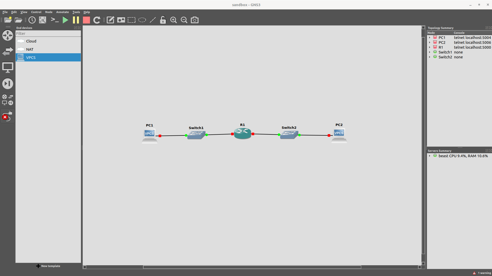
That’s it, out topology is complete. Let’s fire it up and see if everything works. Click on the green “play” button on the top menu. When you do, you should see all of the little circles at each device interface turn green. If so, everything is ready.

In Part 2 of this tutorial we will set up our VPCs with static IP addresses and build out our subnets.